

$2100.91
$0.00
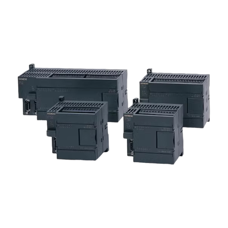
Product details
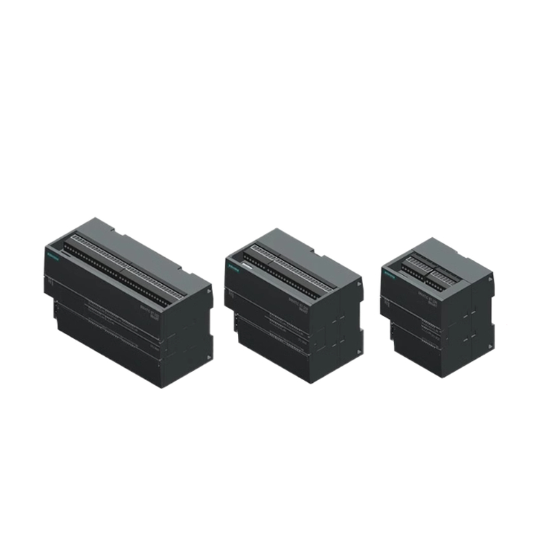
| Technical data | CPU ST20 DCDC/DC | CPU SR20 ACDC/Relay | CPU CR20sACDC/Relay | |||
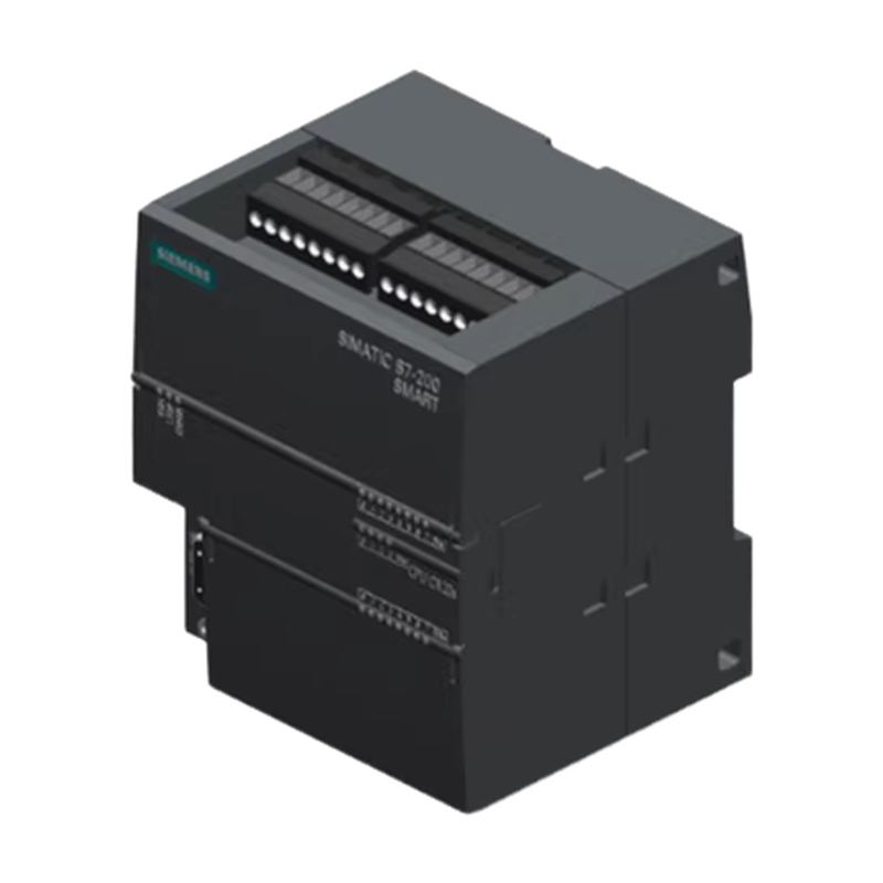
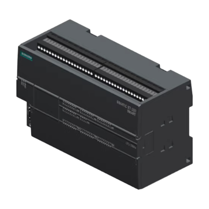
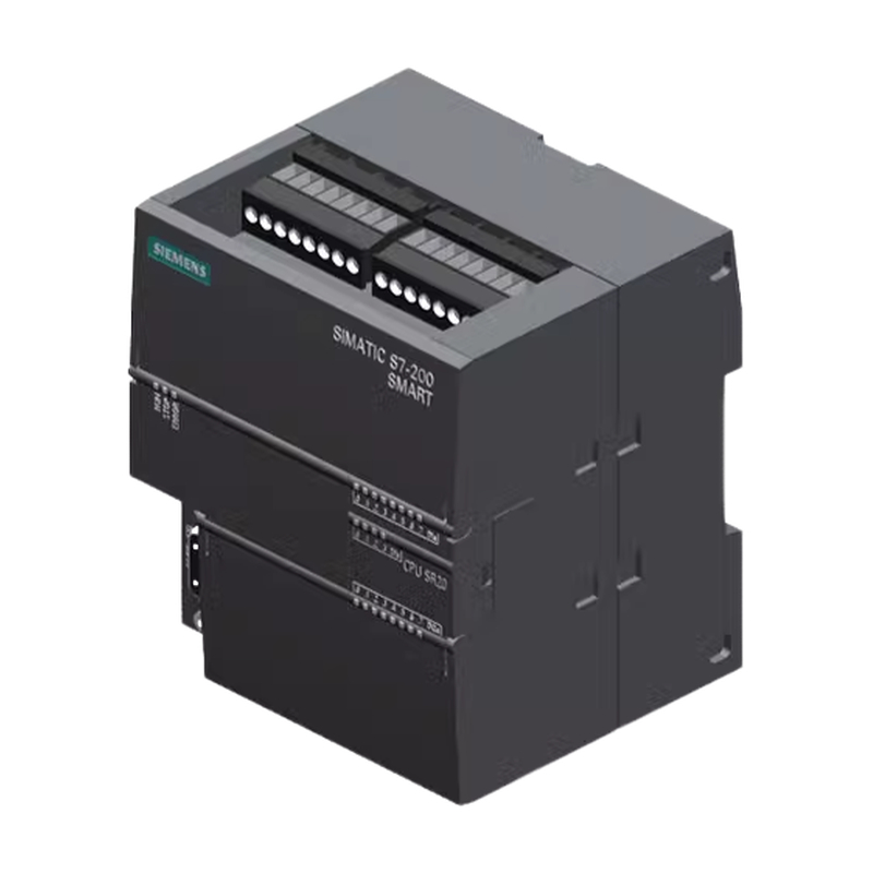
| Article number | 6ES7288-1ST20-0AA1 | 6ES7288-1SR20-0AA1 | 6ES7288-1CR20-0AA1 | |||
| Dimensions WxHxD(mm) | 90×100x81 | 90×100x81 | 90×100x81 | |||
| Weight | 320 grams | 367.3 grams | 363 grams | |||
| Power dissipation | 20W | 14W | 6W | |||
| Current available(EM bus) | 1400 mA max. (5VDO) | 1400 mA max. (5VDC) | Not available | |||
| Current available (24V DC) | 300 mA max. (sensor power) | 300 mA max. (sensor power) | 300 mA max. (sensor power) | |||
| Digital input current con- sumption (24 V DC) | 4 mA/input used | 4 mA/input used | 4 mA/input used | |||
| User mem- ory¹ | Program | 12 Kbytes | 12 Kbytes | 12 Kbytes | ||
| User data (V) | 12 Kbytes | 12 Kbytes | 8 Kbytes | |||
| Retentive | 12 Kbytes max. | 12 Kbytes max. | 2 Kbytes max.1 | |||
| On-board digital I/O | 12 inputs/8 outputs | 12 inputs/8 outputs | 12 inputs/8 outputs | |||
| Process image | 256 bits of inputs (I)/256 bits of outputs (Q) | 256 bits of inputs(I)/256 bits of outputs (Q) | 256 bits of inputs (I)/256 bits of outputs(Q) | |||
| Analog image | 56 words of inputs(Al)/56 words of outputs(AQ) | 56 words of inputs(Al)/56 words of outputs(AQ) | Not available | |||
| Bit memory(M) | 256 bits | 256 bits | 256 bits | |||
| Temporary(local)memory (L) | 64 bytes in the main program and 64 bytes in each subroutine and interrupt rou- tine 60 bytes when programming in LAD or FBD(STEP7- Micro/WIN reserves 4 bytes) | 64 bytes in the main program and 64 bytes in each subroutine and interrupt rou- tine 60 bytes when programming in LAD or FBD(STEP7- Micro/WIN reserves 4 bytes) | 64 bytes in the main program and 64 bytes in each subroutine and interrupt rou- tine 60 bytes when programming in LAD or FBD(STEP7- Micro/WIN reserves 4 bytes) | |||
| Sequential control relays (S) | 256 bits | 256 bits | 256 bits | |||
| Expansion modules expansion | 6 | 6 | Not available | |||
| Signal board expansion | 1 max. | 1 max. | Not available | |||
| High- speed COunters | Total | 6 | 6 | 4 | ||
| Single phase | 4 at 200 kHz 2 at 30 kHz | 4 at 200 kHz 2 at 30 kHz | 4 at 100 kHz | |||
| A/B phase | 2 at 100 Khz 2 at 20 kHz | 2 at 100 Khz 2 at 20 kHz | 2 at 50 kHz | |||
| Pulse outputs ² | 2 at 100 kHz² | 2 at 100 kHz² | Not available | |||
| Pulse catch inputs | 12 | 12 | Not available | |||
| Cyclic interrupts | 2 at 1 ms resolution | 2 at 1 ms resolution | 2 at 1 ms resolution | |||
| Edge interrupts | 4 rising and 4 falling(6 and 6 with optional signal board) | 4 rising and 4 falling (6 and 6 with optional signal board) | 4 rising and 4 falling | |||
| Memory card | microSDHC Card (optional) | microSDHC Card (optional) | Not available | |||
| Real time clock accuracy | +/-120 seconds/month | +/-120 seconds/month | Not available | |||
| Real time clock retention time | 7 days typ./6 days min.at25℃ (maintenance-free Super Ca- pacitor) | 7 days typ./6 days min.at 25℃ (maintenance-free Super Ca- pacitor) | Not available | |||
| Description | CPU ST20 DC/DC/DC | CPU SR20 AC/DC/Relay | ||||
| Support Controller function for PROFINET commu- nication | Yes | |||||
| Support I-Device function for PROFINET communi- cation | Yes | |||||
| Maximum number of PROFINET device | 8 | |||||
| Device number of PROFINET device | 1 to 8 | |||||
| Maximum input size of each PROFINET device | 128 Bytes | |||||
| Maximum output size of each PROFINET device | 128 Bytes | |||||
| Maximum input size of PROFINET I-Device | 128 Bytes | |||||
| Maximum output size of PROFINET I-Device | 128 Bytes | |||||
| Maximum number of modules | 64 | |||||
| Minimum cyclic update time of PROFINET device | The minimum value of the update time also depends on the communi- cation component set for PROFINET,on the number of PROFINET devices, and the quantity of configured user data. | |||||
| CPU address range of PROFINET process image in- put register | 1128.0 to l1279.7 | |||||
| CPU address range of PROFINET process image out- put register | Q128.0 to Q1279.7 | |||||
| CPU address of PROFINET process image input and output register for device #1 | 1128.0 to l255.7 Q128.0 to Q255.7 | |||||
| Description | CPU ST20 DC/DC/DC | CPU SR20 AC/DC/Relay | ||||
| CPU address of PROFINET process image input and output register for device #2 | 1256.0 to 1383.7 Q256.0 to Q383.7 | |||||
| CPU address of PROFINET process image input and output register for device #3 | 1384.0 to 1511.7 Q384.0 to Q511.7 | |||||
| CPU address of PROFINET process image input and output register for device #4 | 1512.0 to 1639.7 Q512.0 to Q639.7 | |||||
| CPU address of PROFINET process image input and output register for device #5 | 1640.0 to 1767.7 Q640.0 to Q767.7 | |||||
| CPU address of PROFINET process image input and output register for device #6 | 1768.0 to 1895.7 Q768.0 to Q895.7 | |||||
| CPU address of PROFINET process image input and output register for device #7 | 1896.0 to l1023.7 Q896.0 to Q1023.7 | |||||
| CPU address of PROFINET process image input and output register for device #8 | 11024.0 to l1151.7 Q1024.0 to Q1151.7 | |||||
| CPU address of PROFINET process image input and output register for I-Device | 11152.0 to l1279.7 Q1152.0 to Q1279.7 | |||||
| Technical data | CPU ST20 DC/DC/DC | CPU SR20 AC/DC/Relay | CPU CR20s AC/DC/Relay | |||
| Number of ports | PROFINET(LAN):1 Serial ports:1(RS485) Add-on serial ports:1(with optional RS232/485 signal board) | PROFINET(LAN):1 Serial ports:1(RS485) Add-on serial ports:1(with optional RS232/485 signal board) | PROFINET(LAN):0 Serial ports:1(RS485) Add-on serial ports:0 | |||
| HMI device | PROFINET(LAN):8 connec- tions Serial ports:4 connections per port | PROFINET(LAN):8 connec- tions Serial ports:4 connections per port | PROFINET(LAN):Not available Serial ports:4 connections per port | |||
| Programming device(PG) | PROFINET(LAN):1 connection Serial ports:1 connection | PROFINET(LAN):1 connection Serial ports:1 connection | PROFINET(LAN):Not available Serial ports:1 connection | |||
| CPUs (PUT/GET) | PROFINET(LAN):8 client and 8 server connections | PROFINET(LAN):8 client and 8 server connections | PROFINET(LAN):Not available | |||
| Open user communication | PROFINET (LAN):8 active and 8 passive connections | PROFINET(LAN):8 active and 8 passive connections | PROFINET(LAN):Not available | |||
| Data rates | PROFINET(LAN):10/100 Mb/s RS485 system protocols: 9600,19200,and 187500 b/s RS485 freeport:1200 to 115200 b/s | PROFINET(LAN):10/100 Mb/s RS485 system protocols: 9600,19200,and 187500 b/s RS485 freeport:1200 to 115200 b/s | PROFINET(LAN):Not available RS485 system protocols: 9600,19200,and 187500 b/s RS485 freeport:1200 to 115200 b/s | |||
| Isolation(external signal to PLC logic) | PROFINET(LAN):Transformer isolated,1500VAC RS485: RS485 signal to chassis ground,500VAC/707VDC; RS485 signal to CPU logic com- mon,500 V AC/707V DC; | PROFINET(LAN):Transformer isolated,1500V AC RS485: RS485 signal to chassis ground,500VAC/707VDC; RS485 signal to CPU logic com- mon,500 V AC/707V DC; | PROFINET(LAN):Not available RS485: RS485 signal to chassis ground,500VAC/707VDC; RS485 signal to CPU logic com- mon,500VAC/707V DC; | |||
| Cable type | PROFINET(LAN):CAT5e shiel- ded RS485:PROFIBUS network ca- ble | PROFINET(LAN):CAT5e shiel- ded RS485:PROFIBUS network ca- ble | PROFINET(LAN):Not available RS485:PROFIBUS network ca- ble | |||
| PROFINET Communication | ||||||
| PROFINET controller | Yes | Yes | No | |||
| PROFINET device | Yes | Yes | No | |||
| PROFINET controller | ||||||
| Services | ||||||
| PG/OP communication | Yes | Yes | No | |||
| S7 routing | Yes | Yes | No | |||
| Isochronous mode | No | No | No | |||
| Open IE communication | Yes | Yes | No | |||
| IRT | No | No | No | |||
| MRP | No | No | No | |||
| PROFlenergy | No | No | No | |||
| Technical data | CPU ST20 DC/DC/DC | CPU SR20 AC/DC/Relay | CPU CR20s AC/DC/Relay | |||
| Max.number of PROFINET devices that you can con- nect for RT | 8 | 8 | -- | |||
| Max.number of module | 64 | 64 | -- | |||
| Update times | The minimum value of the up- date time also depends on the communication component set for PROFINET,on the num- ber of PROFINET devices,and the quantity of configured user data. | The minimum value of the up- date time also depends on the communication component set for PROFINET,on the num- ber of IO devices,and the quantity of configured user da- ta. | No | |||
| With RT | ||||||
| Send clock of 1 ms | 1 ms to 512 ms | 1 ms to 512 ms | -- | |||
| Voltage range | 20.4 to 28.8V DC | 85 to 264 V AC | 77 to 138V DC | 85 to264 VAC | 77 to 138 V DC | |
| Line frequency | -- | 47 to 63 Hz | -- | 47 to 63 Hz | -- | |
| Input current | CPU only at max. load | 160 mA at 24 V DC(without driv- ing 300 mA sen- sor power) 430 mA at 24 V DC(with driving 300 mA sensor power) | 210 mA at 120VAC(with 300 mA power sensor output) 90 mA at 120 VAC(with- out 300 mA power sensor output) 120 mA at 240VAC(with 300 mA power sensor output) 60 mA at 240VAC(with- out 300 mA power sensor output) | 120 mA at 110 VDC (with 300 mA power sensor output) 44 mA at 110VDC(with- out 300 mA power sen- sor output) | 90 mA at 120 VAC 60 mA at 240 V AC | 120 mA at 110 VDC (with 300 mA power sensor output) 44 mA at 110 VDC (without 300 mA pow- er sensor output) |
| CPU with all expan- sion accessO- ries at max.load | 720 mAat24VDC | 290 mA at 120 VAC 170 mA at 240VAC | 207 mA at 110 VDC (with 300 mA power sensor output) | -- | 207 mA at 110 VDC (with 300 mA power sensor output) | |
| Hold up time (loss of power) | 20 ms at 24V DC | 30 ms at 120 V AC 200 ms at 240 VAC | 30 ms at 110V DC | 30 ms at 120 VAC 200 ms at 240 VAC | 30 ms at 110V DC | |
| Inrush current (max.) | 11.7A at 28.8V DC | 9.3A at 264VAC | 16.3A at 264V AC | |||
| Isolation(inputpower to logic) | -- | 1500 VAC | 1500VAC | |||
| Ground leakage,AC line to functionalearth | -- | 0.5 mA max. | 0.5 mA max. | |||
| Internal fuse,not user replaceable | 3A,250V slow blow | 3A,250V,slow blow | 3A,250V,slow blow | |||
| Technical data | CPU ST20 DC/DC/DC | CPU SR20 AC/DC/Relay | CPU CR20s AC/DC/Relay | |||
| Voltage range | 20.4 to 28.8V DC | 20.4 to 28.8V DC | 20.4 to 28.8V DC | |||
| Output current rating (max.) | 300 mA(short circuit protected) | 300 mA(short circuit protected) | 300 mA(short circuit protected) | |||
| Maximum ripple noise (<10 MHz) | <1V peak to peak | <1V peak to peak | <1V peak to peak | |||
| Isolation(CPU logic to sensor power) | Not isolated | Not isolated | Not isolated | |||
| Number of inputs | 12 | 12 | 12 | |||
| Type | SinkSource (IEC Type 1 sink, except l0.0 to l0.3,10.6 to l0.7) | Sink/Source(IEC Type 1 sink) | Sink/Source(IEC Type 1 sink) | |||
| Rated voltage | 24 V DC at 4 mA,nominal | 24 V DC at 4 mA,nominal | 24 V DC at 4 mA,nominal | |||
| Continuous permissible voltage | 30V DC,max. | 30V DC,max. | 30V DC,max. | |||
| Surge voltage | 35V DC for 0.5 sec | 35V DC for 0.5 sec. | 35V DC for 0.5 sec. | |||
| Logic 1 signal(min.) | 10.0 to 10.3,10.6 to l0.7:4VDC at 8 mA Other inputs:15VDC at 2.5 mA | 15V DC at 2.5 mA | 15V DC at 2.5 mA | |||
| Logic O signal(max.) | 10.0 to 10.3,10.6 to 10.7:1VDC at 1 mA Other inputs:5V DC at 1 mA | 5V DC at 1 mA | 5V DC at 1 mA | |||
| Isolation (field side to logic) | 500 V AC for 1 minute | 500VAC for 1 minute | 500 VAC for 1 minute | |||
| Isolation groups | 1 | 1 | 1 | |||
| Technical data | CPU ST20 DC/DC/DC | CPU SR20 AC/DC/Relay | CPU CR20s AC/DC/Relay | |||
| Filter times | Individually selectable on each channel(points 10.0 to l1.3): μs:0.2,0.4,0.8,1.6,3.2,6.4, 12.8 ms:0.2,0.4,0.8,1.6,3.2,6.4, 12.8 | Individually selectable on each channel(points 10.0 to l1.3): μs:0.2,0.4,0.8,1.6,3.2,6.4, 12.8 ms:0.2,0.4,0.8,1.6,3.2,6.4, 12.8 | Individually selectable on each channel(points 10.0 to l1.3): μs:0.2,0.4,0.8,1.6,3.2,6.4, 12.8 ms:0.2,0.4,0.8,1.6,3.2,6.4, 12.8 | |||
| HSC clock input rates (max.) | Single phase:4 HSCs at 200 kHz;2 HSCs at 30 kHz A/B phase:2 HSCs at 100 kHz; 2 HSCs at 20 kHz | Single phase:4 HSCs at 200 kHz;2 HSCs at 30 kHz A/B phase:2 HSCs at 100 kHz; 2 HSCs at 20 kHz | Single phase:4 HSCs at 100 kHz A/B phase:2 HSCs at 50 kHz | |||
| Number of inputs on simultaneously | 12 | 12 | 12 | |||
| Cable length (max.) in meters | 10.0 to 10.3: Shielded (only): · 500 m normal(low-speed) inputs ·50m HSC(high-speed)in- puts | All inputs: Shielded: · 500 m normal inputs · 50 m HSCinputs Unshielded: · 300 m normal inputs | All inputs: Shielded: · 500 m normal inputs, · 50m HSC inputs Unshielded: ·300 m normal inputs | |||
| 10.6 to I0.7: ·Shielded (only):500 m normal inputs | ||||||
| All other inputs: · Shielded:500 m normal inputs ·Unshielded:300m normal inputs | ||||||
| Number of outputs | 8 | 8 | 8 | |||
| Type | Solid state-MOSFET(sourcing) | Relay,dry contact | Relay,dry contact | |||
| Voltage range | 20.4 to 28.8V DC | 5 to 30VDC or 5 to 250 V AC | 5 to 30 VDC or 5 to 250VAC | |||
| Logic 1 signal at max. current | 20V DC min. | -- | -- | |||
| Logic O signal with 10 KQ load | 0.1 VDC max. | -- | -- | |||
| Rated current per point (max.) | 0.5A | 2.0 A | 2.0A | |||
| Rated current per common (max.) | 6A | 10.0 A | 10.0 A | |||
| Lamp load | 5W | 30 W DC/200 WAC | 30 WDC/200 WAC | |||
| ON state resistance | 0.6Ωmax. | 0.2Q max.when new | 0.2Q max.when new | |||
| Leakage current per point | 10 μA max. | -- | -- | |||
| Surge current | 8A for 100 ms max. | 7A with contacts closed | 7A with contacts closed | |||
| Overload protection | No | No | No | |||
| Isolation(field side to logic) | 500 V AC for 1 minute | 1500VAC for 1 minute(coil to contact) None (coil to logic) | 1500VAC for 1 minute(coil to contact) None (coil to logic) | |||
| Isolation resistance | -- | 100 MQ min.when new | 100 MQ min.when new | |||
| Isolation between open contacts | -- | 750VAC for 1 minute | 750VAC for 1 minute | |||
| Isolation groups | 2 | 1 | 1 | |||
| Inductive clamp voltage | L+minus 48V DC, 1 W dissipation | Not recommended | Not recommended | |||
| Switching delay(Qa.0 to Qa.3) | 1.0 μs max.,off to on 3.0 μs max.,on to off | 10 ms max. | 10 ms max. | |||
| Switching delay(Qa.4 to Qa.7) | 50μs max.,off to on 200 μs max.,on to off | 10 ms max. | 10 ms max. | |||
| Maximum relay switching frequency | -- | 1 Hz | 1 Hz | |||
| Lifetime mechanical(no load) | -- | 10,000,000 open/close cycles | 10,000,000 open/close cycles | |||
| Lifetime contacts at rated load | -- | 100,000 open/close cycles | 100,000 open/close cycles | |||
| Output state in STOP mode | Last value or substitute value (default value O) | Last value or substitute value (default value O) | Last value or substitute value (default value O) | |||
| Number of outputs on simultaneously | 8 | 8 | 8 | |||
| Cable length (max.), in meters | Shielded:500 m Unshielded:300 m | Shielded:500 m Unshielded:300 m | Shielded:500 m Unshielded:300 m | |||
CUSTOMER REVIEWS
0 Reviews
Frequently Bought Together
JOIN OUR NEWSLETTER
Sign up for first access to new products, sales and events.